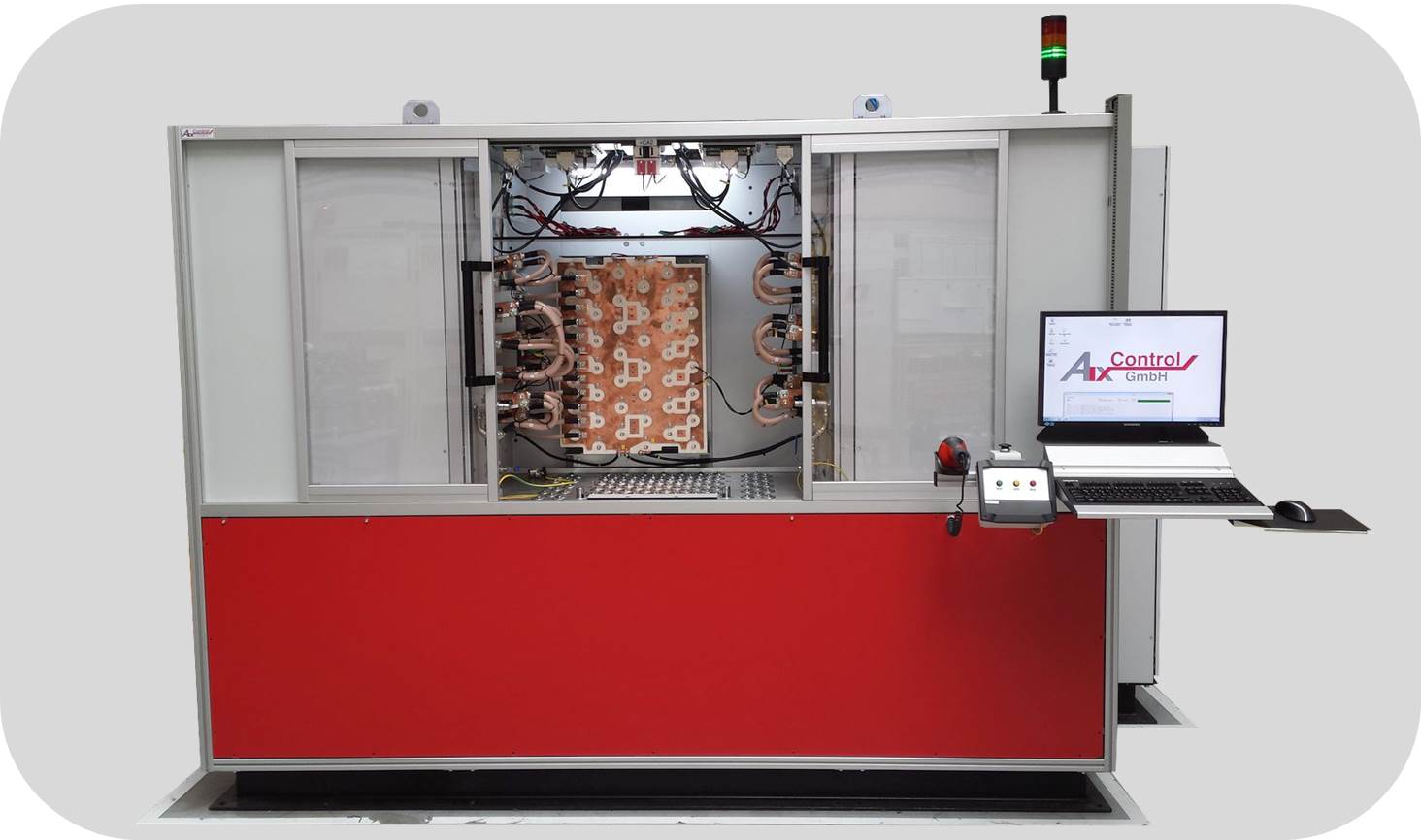
Specific Stack Test Bench
The AixControl Stack Test Bench (XSTB) is designed for the end-of-line test of DUTs (mainly Power Electronic Stacks). With its closed test cabinet the test bench can be directly placed in the production area. The testbench can be equipped with various loading and quick connection options.
AixControl has wide experience on customer specific solutions, not only for connection and handling of the DUTs, but also for testing and programming individual functionality.
- Specific for one DUT
- Safe due to closed cabinets
- Up to 2000 A, 1500 V
- EOL test of DUT’s function and protection
- Thermal cycling
- Test of customer specific functions
Operation:
After the DUT is scanned, it can be loaded and quick connected to the test bench. The operator shuts the safety doors and pushes the start button.
The test bench executes the predefined test sequence. The set points and evaluation limits are chosen according to the type of DUT. The test result is indicated by signal light.
Besides individually implemented test modules for the customers's specific needs, the following test are commonly offered:
FLOW TEST
The flow test checks, that the liquid connections are properly established and the cooling system is working. Therefore, the cooling system is enabled, the inlet temperature of the cooling fluid is set and a sequence of flow rates run through. The test verifies, that the flow rate, temperature and pressure delta are in the specified limits whithin a configurable timeout.
DIELECTRIC TEST
The dielectric test verifies the insulation of the DUT by measuring the leakage current at high potential. All power connections (dc+, dc-, ac-outputs if available) are connected to a high dc potential. The driver boards and heatsink remain on ground potential. The leakage current is measured and compared to limits. The test is performed with bipolar voltages.
DRIVER CONSUMPTION TEST
The driver consumption test verifies the driver's current consumption in idle state and during PWM switching.
PULSE TEST
The pulse test can be run with three different operation modes:
- Functional-Switching (FSW) mode checks, if the semiconductors are switching in general. The load chokes are in the current path. The dc link voltage is limited.
- Over-Current-Protection (OCP) tests the over-current monitoring (“soft short circuit” can be checked). The current path is conducted via the load inductances.
- Dynamic-Short-Circuit-Protection (DSCP) mode observes the correct behavior of the driver stage in respect of a hard short circuit. The current path is conducted directly from the IGBT-output to the DC-link, without the load inductances being involved.
- Active-Clamping (ACL) mode tests the active clamping functionality of the driver board can be tested by measuring the gate-emitter-voltage of the IGBT. The load inductance in the current path is reduced.
THERMAL CYCLING TEST
In this power test the DUT is run against the test-stand reference stack to simulate real operation. The power is flowing in a circle over the dc-link and output phases, only losses are fed into the dc-link by the PSU. For an inverter sinusoidal current profiles can be defined, for the brake chopper dc current can be selected.
SLOW DISCHARGE TEST
This test is used to estimate the capacitance of a c-bank. The dc-link is charged to a certain voltage, then it is slowly discharged by connecting dedicated slow discharge resistors. After a specified discharge time the dc-link voltage is compared to limits.